Wiring Diagram Ofdomestic Electrical House Installation / Electrical / There are three stages for house wiring:. White and gray wires are neutral wires that connect to the neutral bus bar. Black wires or hot wires carry live electrical loads from the electrical service panel to an outlet, light or other destination.; Wiring diagrams, device locations and circuit planning. The load on 3 phases should be properly balanced. It shows how electrical items and wires connect, where the lights, light switches, socket outlets, and the appliances are located.
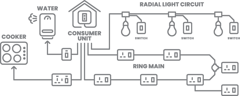
Grey= phase 1 or line1, black= line 2, brown= line 3, blue = neutral and green= earth conductor. Radial lighting circuits from 6a cu mcbs. These are mainly used for indoor installations. 2 or more circuits typical. Less safety poor appearance cant used it for permanent installation 16.
Home Wiring Guide Arlec Uk from www.arlec.co.uk Single line diagram electrical house wiring house wiring diagram of a typical circuit electrician describes a typical home electrical circuit in detail using a basic house wiring diagram it shows the … Electrical schematic diagram elementary wiring a2z. Wiring diagrams, device locations and circuit planning. Load current = total lighting circuit load/voltage = 760/230 = 3.30 amps. To know the cause of failure of a particular circuit or circuits or. The load on 3 phases should be properly balanced. The following is sort of an electrical wire types chart: Circuit diagrams of wiring in the residential building a1 switchgear must comply with the requirements of as sadales tīkls and must be located outside the object's territory so that it is easy accessible by an inspector.
Circuit diagrams of wiring in the residential building 3.
It is important to maintain these units in their weatherproof condition until the building is fully enclosed. Below quotation given by my electrical contractor during my house construction. A typical set of house plans shows the electrical symbols that have been located on the floor plan but do not provide any wiring details. The house electrical plan is one of the most critical construction blueprints when building a new house. Electrical circuit diagram house wiring transpa cartoon jing fm. If you look closely at the picture of the electric meter, you will notice that there is actually a pair of electric. Single line diagram how to represent the electrical installation of a house stacbond. A fuse is an electrical part which you can't see as it's always inside a plug or an electrical device such as tv. The main reasons, to test a new electrical installation or house wiring before it is switched on to the mains are as follows:. 50 hz, 4 wire supply should be used. Fault can be easily identify materials collected after removal of installation can be used for further wiring expansion of wiring is possible disadvantages: Below is the given wiring diagram of single phase distribution board with rcd in both nec and iec electrical wiring color codes. Wiring diagrams, device locations and circuit planning.
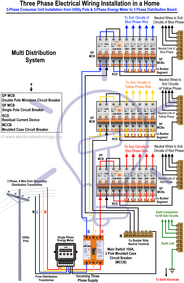
50 hz, 4 wire supply should be used. In the domestic wiring earth wire should be of 14 swg gi for single phase supply and for 3 phase supply system earth wire must be of 8 swg gi. If the load on any domestic wiring installation exceeds 6.0 kw. If you look closely at the picture of the electric meter, you will notice that there is actually a pair of electric. Circuit diagrams of wiring in the residential building 3.
Three Phase Electrical Wiring Installation In Home Nec Iec from www.electricaltechnology.org Single line diagram how to represent the electrical installation of a house stacbond. Wiring diagrams, device locations and circuit planning. White and gray wires are neutral wires that connect to the neutral bus bar. This electrical part is a small length thin wire created using lead and tin alloy. There are three stages for house wiring: 2 or more circuits typical. 50 hz, 4 wire supply should be used. To calculate any size of the wire, first, we should calculate load current and by using a wire table size of the wire can be calculated.
21 do not wear loose clothing or ties near electrical equipment.
Let, a factor of safety be 2(for future demands or load) current rating = load current * 2 = 3.30 * 2 = 6.6 amps There are three stages for house wiring: In the domestic wiring earth wire should be of 14 swg gi for single phase supply and for 3 phase supply system earth wire must be of 8 swg gi. Free house wiring diagram software edrawmax online. Electrical circuit diagram house wiring transpa cartoon jing fm. Example 1 of a single phase consumer electrical wiring is as shown in figure 3.2 2 The main reasons, to test a new electrical installation or house wiring before it is switched on to the mains are as follows:. 2 or more circuits typical. Radial lighting circuits from 6a cu mcbs. The following are the proper steps to follow when wiring your house. The following is sort of an electrical wire types chart: Grey= phase 1 or line1, black= line 2, brown= line 3, blue = neutral and green= earth conductor. 2 or more circuits typical.
Draw a schematic labelled diagram of domestic electric circuit studyrankersonline. Free house wiring diagram software edrawmax online. This one is the most basic principle of a house wiring installation. These are mainly used for indoor installations. Act like an electrical engineer, you are not on the beach.
House Wiring Diagram Of A Typical Circuit from thecircuitdetective.com In a typical new town house wiring system, we have: Underground stage rough stage electrical stage from the power company, we get: The main reasons, to test a new electrical installation or house wiring before it is switched on to the mains are as follows:. Single line diagram electrical house wiring house wiring diagram of a typical circuit electrician describes a typical home electrical circuit in detail using a basic house wiring diagram it shows the … Electrical schematic diagram elementary wiring a2z. Two hot wires one neutral wire. Circuit diagrams of wiring in the residential building 3. This wiring installation is simple and cheap as compared to other electrical wiring systems also takes less time to install.
Below quotation given by my electrical contractor during my house construction.
In a typical new town house wiring system, we have: The house electrical plan is one of the most critical construction blueprints when building a new house. 2 such rings is typical for a 2 up 2 down, larger houses have more. A typical set of house plans shows the electrical symbols that have been located on the floor plan but do not provide any wiring details. The main reasons, to test a new electrical installation or house wiring before it is switched on to the mains are as follows:. The electric toolkit provides some basic electrical calculations, wiring diagrams (similar to those found on this website), and other electrical reference data. Below is the given wiring diagram of single phase distribution board with rcd in both nec and iec electrical wiring color codes. Electrical circuit diagram house wiring transpa cartoon jing fm. Draw a schematic labelled diagram of domestic electric circuit studyrankersonline. For simple electrical installations we commonly use this house wiring diagram. White and gray wires are neutral wires that connect to the neutral bus bar. Below quotation given by my electrical contractor during my house construction. 2 or more circuits typical.